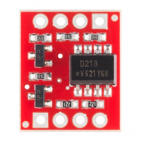

This optoisolator is configured for data rates up to 9600bps. What you put into the IN pins, will be replicated on the the OUT pins, but at the higher voltage (HV).

We threw some transistors on this compact board to correct the inversion. Great for use in noisy circuits where signal lines require electrical isolation.Ī normal LED opto-isolator will invert the logic of a signal. This breakout board uses the ILD213T optoisolator and discrete transistors to correct the logic. This board is helpful for connecting digital systems (like a 5V microcontroller) to a high-voltage. This board will isolate the systems, creating a type of electrical noise barrier between devices. Description: This is a board designed for opto-isolation. We often use this board to allow a microcontroller control servos or other motors that use a higher voltage than the TTL logic on the (3.3V or 5V) micro, and may cause electromagnetic interferance with our system as the motors turn on and off. This allows the low-voltage side to control a high voltage side. This IC has two LEDs and two photodiodes built-in. This board electrically isolates a controller from the high-power system by use of an opto-isolator IC.

Features, Specifications, Alternative Product, Product Training Modules, and Datasheets are all available. This board is helpful for connecting digital systems (like a 5V microcontroller) to a high-voltage or noisy system. Browse DigiKeys inventory of Card ReaderRFID Reader Modules. This board is helpful for connecting digital systems (like a 5V microcontroller) to a high-voltage or noisy system.
#TTL OPTICAL ISOLATOR SPARKFUN SOFTWARE#
But then maybe you will never be turning on all 8 solenoids at the same time?Īlso keep in mind that those relay channels will turn on when there is a LOW output applied from each arduino digital output pin and the relay channel will turn off when a HIGH is output, but that's just software state to keep in mind.This is a board designed for opto-isolation. This is a board designed for opto-isolation. That make sense? I would get a little more 'husky' 12vdc power modules, maybe rated at 2 amps or better as you really don't want to run one close to it's maximum capacity if you can help it. Then the normally open contact of each relay wires to it's specific solenoid and then all the solenoid return wires get wired together and attached to the DC modules negative. Here, the Tx unit is a LED, but the Rx unit may take the form of a phototransistor, a photo. Figure 1 shows the basic form of such a device. Well one would normally run a 'daisy chain' for the +12vdc, that is run one wire from the positive of the power module to the first relays common terminal then jumper from that common terminal to the next relays common terminal and then on to the next, until all eight have +12vdc applied to their common contacts. An optocoupler device can be simply described as a sealed, self-contained unit that houses independently-powered optical (light) Tx and Rx units, that can be coupled together optically.

So I connect the relay module's VCC to the arduino's 5v out, and the relay module's GND to the arduino's GND out, right? Then, does each relay's COM pin get connected to the 12v on the power supply? So my power supply would need to be spliced 32 times!?


 0 kommentar(er)
